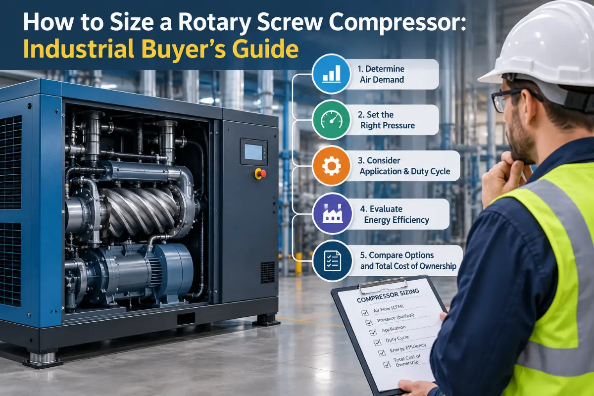
Sizing a rotary screw compressor starts with four numbers: the plant’s actual air demand, the minimum pressure required at the point of use, the way demand changes over time, and the air quality the process needs. Motor horsepower comes later. In my view, the most expensive sizing errors happen when a buyer selects from horsepower, copies the nameplate of an old compressor, or adds every pneumatic tool’s maximum CFM as if all tools run continuously. A sound rotary screw compressor sizing process separates base demand from short peaks, accounts for real pressure losses, checks the compressor’s rated free air delivery at the required pressure, and then chooses a control strategy that fits the load profile. This guide shows how I’d build that decision from operating data rather than catalog shortcuts.
The Short Answer: Size Airflow at the Pressure You Actually Need
A compressor is correctly sized when it can deliver the required usable airflow at the required discharge pressure without spending most of its life either starved for capacity or wasting power in an inefficient control state. That sounds simple, but “required airflow” is rarely one number. A plant may have a 260 CFM base load, a 400 CFM normal production load, and a 550 CFM peak that lasts only 20 seconds. Those three conditions should not automatically produce the same equipment choice as a plant that consumes 550 CFM continuously.
I’d reduce the sizing process to the following engineering sequence:
Establish demand: determine minimum, normal, and peak airflow in CFM, SCFM, or m³/min.
Establish pressure: start from the minimum pressure needed at the most demanding point of use, then add only defensible system losses and a control margin.
Match the load profile: decide whether fixed-speed, VSD/VFD, two-stage compression, multiple compressors, storage, or a combination fits the way demand moves.
Verify rated performance: compare free air delivery and package input power at the same operating pressure and stated test conditions.
Check the complete system: include dryers, filters, receivers, distribution pressure drop, electrical supply, cooling, ambient conditions, maintenance access, and redundancy.
The key point is that compressor size is not just “how many horsepower.” It is how much usable air, at what pressure, for how long, under what operating conditions.
What “Compressor Size” Actually Means
Industrial quotations often begin with a request such as “We need a 75 HP screw compressor.” I would treat that as a starting clue, not a complete specification. Two compressors with the same motor rating can produce different airflow at the same pressure, and the same compressor family can produce less flow as its rated pressure increases. The buyer therefore needs to compare output, pressure, and package power together.
| Input | What It Controls | What I Would Ask For | Common Buying Error |
|---|---|---|---|
| Airflow | Compressor capacity | Minimum, normal, and peak demand in CFM/SCFM or m³/min | Adding all connected tools at maximum consumption |
| Pressure | Required compression ratio and available flow | Minimum pressure at the point of use plus measured or calculated losses | Matching the old compressor’s discharge setting without checking the process |
| Demand profile | Control method and number of compressors | Flow and pressure trend over representative production periods | Sizing one large machine for a short-duration peak |
| Air quality | Dryer, filters, oil-free requirement, and pressure drop | Required pressure dew point and contamination limits | Specifying treatment after the compressor is already selected |
| Site conditions | Cooling margin, inlet density, reliability, and electrical configuration | Ambient temperature, elevation, dust, humidity, ventilation, and power supply | Using sea-level catalog output without checking correction data |
| Future capacity | Expansion allowance | Known machines, production lines, and commissioning dates | Adding an arbitrary large percentage “just in case” |
CAGI’s 2022 Rotary Air Compressor Selection Guide identifies air demand, air pressure, and air quality as the three critical system variables and recommends assessment of both supply and demand before equipment selection. That hierarchy is still the right place to begin because it keeps the conversation centered on the system rather than the motor nameplate. Source: CAGI, 2022.
Step 1: Build a Real Compressed-Air Demand Profile
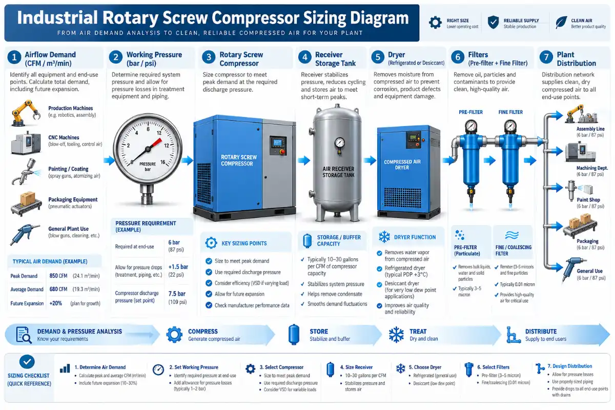
For an existing plant, measured demand is more persuasive than theoretical demand. For a new plant, calculated demand is unavoidable, but the calculation should reflect how equipment actually operates. I’d separate the job into base demand, normal production demand, short peaks, and future known loads. That makes the later choice between fixed-speed capacity, variable-speed trim, storage, and standby capacity much easier.
Existing plants: measure before replacing
If production is already running, I’d recommend logging system pressure and airflow through representative shifts rather than selecting a replacement from the old compressor’s horsepower. A week of data is often more useful than one gauge reading because it reveals breaks, shift changes, batch cycles, weekend load, simultaneous machine starts, and abnormal events.
The most useful field measurements are straightforward:
flow at the compressor-room header or another representative main;
pressure at the compressor discharge, main header, and critical point of use;
compressor loaded, unloaded, or speed percentage status;
package input power where practical;
dryer and filter differential pressure;
production state, so the data can be tied to actual operating conditions.
A thermal mass flow meter, insertion flow meter, pressure transducers, and a power logger can turn a subjective discussion into an engineering load profile. I’d also save a screenshot or exported trend showing at least one normal production cycle. The important question is not only the highest CFM observed. It is how long the system stays at each demand level.
New plants: calculate connected load, then apply realistic use factors
For a new installation, begin with each air-using device. Record the manufacturer’s air consumption at the required inlet pressure, quantity installed, expected duty factor, and expected simultaneity. CAGI’s 2022 guide describes the same basic logic: determine maximum demand for each device, apply a use factor, and sum the adjusted loads. I would add one more discipline—keep short high-flow events separate instead of burying them inside a single average.
A practical planning formula is:
Estimated average demand = Σ (device airflow × quantity × use factor × simultaneity factor)
Use factors and simultaneity factors are project assumptions, not universal constants. They should come from machine cycle data, production planning, OEM documentation, or comparable process knowledge. If a cylinder uses a burst of air for two seconds every 20 seconds, treating its maximum instantaneous flow as a continuous load can oversize the compressor badly. At the same time, averaging too aggressively can hide a peak that causes unacceptable pressure sag.
Separate base, normal, and peak demand
| Demand Level | Typical Meaning | What It Should Influence | What I Would Avoid |
|---|---|---|---|
| Minimum / base | Air used whenever the plant is running | Base-load compressor size and minimum VSD operating range | Running a large VSD below its efficient controllable range |
| Normal | Most common production condition | Primary operating point for energy comparison | Optimizing only for the theoretical maximum |
| Peak | Highest simultaneous demand | Total available capacity, storage, and pressure stability | Assuming every peak must be met by compressor displacement alone |
| Future known load | Approved or reasonably defined expansion | Reserve, piping, electrical capacity, and staged expansion plan | Buying excessive idle capacity for undefined growth |
One subtle point matters here: a leak is real demand, but I would not automatically treat a known avoidable leak load as permanent productive capacity. If the plant needs 420 CFM of process air and currently leaks another 80 CFM, purchasing a compressor solely to preserve that 80 CFM of waste can lock the inefficiency into the new design. The better procurement file shows productive demand, unavoidable demand, known leakage, and expansion as separate lines.
Step 2: Determine the Required Working Pressure Without Inflating It
Airflow and pressure are inseparable. A compressor rated for a certain CFM at 100 psi cannot be assumed to deliver the same CFM at 145 psi. Higher discharge pressure also raises energy consumption and often increases leakage or other unregulated air use. That is why I’d start at the equipment, not at the compressor.
Build a pressure budget from the most demanding legitimate user:
Required compressor discharge pressure = minimum point-of-use pressure + treatment loss + piping/distribution loss + control margin
Suppose a critical machine needs 90 psig at its inlet during production. The dryer and filters account for 5 psi under design flow, distribution adds 6 psi to the remote machine, and the control scheme needs a 4 psi operating margin. The preliminary compressor discharge target becomes 105 psig. I would then verify each loss under peak flow before specifying a 125 psig or 145 psig machine simply because that rating is common.
The 2016 third edition of Improving Compressed Air System Performance gives a useful rule of thumb near 100 psig: every 2 psi increase in discharge pressure can raise full-output energy consumption by about 1%. The same source explains that the penalty can be larger once pressure-sensitive unregulated demand is included; in an example range with 30–50% unregulated usage, the combined increase is about 1.6–2% for each 2 psi increase. Those figures are system-level rules of thumb, not a substitute for a compressor performance curve, but they illustrate why “a little extra pressure” should be justified. Source: Compressed Air Challenge / Department of Energy, Third Edition, 2016.
Do not solve a local pressure problem by raising the whole plant
If one machine at the end of the distribution network loses pressure during a short event, the root cause may be undersized branch piping, a restrictive filter, a small hose, a regulator, a quick coupling, insufficient local storage, or simultaneous flow. Raising the compressor setpoint may conceal the restriction while increasing operating cost everywhere else. I’d want pressure measurements upstream and downstream of the suspected restriction during the event before changing the compressor rating.
Pressure drop should also be evaluated at design flow, not at idle. A clean filter with negligible differential pressure today may have a higher allowable pressure drop at its maintenance limit. The purchase specification should state the assumed clean and service-limit losses where those figures matter to the pressure budget.
Step 3: Compare CFM, SCFM, ACFM, and Free Air Delivery Correctly
Many bad comparisons begin with units that look similar but are not defined the same way. CFM by itself can be ambiguous. SCFM refers to a standardized reference condition, but the exact standard condition should be stated. ACFM describes actual volumetric flow at actual inlet conditions. FAD, or free air delivery, is commonly used to express compressor output referenced back to specified inlet conditions.
For purchasing, I’d ask for the compressor’s rated delivered airflow at the required operating pressure under a recognized test method. ISO 1217:2009 specifies acceptance-test methods for volume flow rate and power requirements of displacement compressors; the published edition was confirmed in 2021 and remains the current published edition while a revision is under development. Source: ISO 1217:2009, confirmed 2021.
CAGI’s Performance Verification Program also uses ISO 1217 procedures for rotary compressor performance verification and provides a standardized framework for comparing published capacity and specific power. In my view, this is the right mindset even when a supplier does not participate in that program: ask for the test basis, rated pressure, rated flow, and package input power together. Source: CAGI Performance Verification, accessed 2026.
| Quantity | Useful Conversion | Purchasing Note |
|---|---|---|
| Airflow | 1 m³/min ≈ 35.315 CFM | Confirm whether the quoted value is FAD, SCFM, or another defined basis. |
| Pressure | 1 bar ≈ 14.504 psi | Confirm gauge vs. absolute pressure; compressor catalogs normally use gauge pressure for working pressure. |
| Power | 1 kW ≈ 1.341 hp | Do not infer airflow from motor power alone. |
| Storage | 1 ft³ ≈ 28.317 L | Receiver volume only becomes useful when pressure range and event duration are known. |
Specific power deserves attention because it connects electrical input to delivered air. A common expression is kW per 100 CFM at a stated discharge pressure. Lower specific power at the same valid test point generally indicates less input power for the same output, but the comparison must be made at equivalent pressure and conditions. A machine rated at lower pressure should not be declared more efficient than another machine rated at higher pressure without correcting the comparison.
Step 4: Add Reserve Intelligently, Not Automatically
“Add 25% for safety” is one of the sizing habits I would challenge first. Sometimes 25% is justified. Sometimes 10% is enough. Sometimes even 25% does not cover a defined expansion. The right reserve comes from uncertainty and business plans, not from a universal percentage.
I’d separate reserve into three categories:
Measurement uncertainty: allowance for imperfect estimates or instrumentation.
Known growth: additional equipment or production already planned.
Operational resilience: capacity required during maintenance, a compressor outage, filter loading, or abnormal production.
Those three risks are solved differently. Measurement uncertainty may justify a modest capacity margin. Known growth may justify larger piping, spare electrical capacity, or room for an additional compressor. Resilience may justify N+1 capacity or multiple smaller machines rather than one oversized unit.
Short peaks may belong in storage, not motor size
A receiver can supply air during a brief event as system pressure falls through an acceptable range. For a simplified isothermal estimate, the receiver volume needed to cover a temporary airflow shortfall can be approximated by:
Receiver volume (ft³) ≈ shortfall flow (SCFM) × event time (min) × 14.7 / allowable pressure drop (psi)
For example, suppose a process needs an extra 120 SCFM for 20 seconds, and the local storage can fall from 110 psig to 100 psig during that event. The shortfall volume is 120 × 0.333 ≈ 40 standard cubic feet. Using the simplified formula gives about 58.8 ft³ of receiver volume, or roughly 1,665 liters. That is an illustrative thermodynamic estimate, not a final vessel specification; temperature effects, regulator behavior, control response, code requirements, and usable pressure range still need to be checked.
In my view, storage earns its place when it solves a time problem. A receiver cannot compensate indefinitely for a compressor that is too small. If demand exceeds compressor capacity for ten seconds, storage may be effective. If demand exceeds capacity for six hours, more sustainable compressor capacity is required.
Fixed-Speed, VSD, or Two-Stage: Match the Machine to the Load Profile
Once airflow and pressure are known, control strategy becomes a sizing issue rather than a feature comparison. I would not choose a VSD compressor merely because demand is “variable,” and I would not choose fixed speed merely because the purchase price is lower. The useful question is how much time the system spends at each flow level and how the selected machine behaves there.
| Operating Pattern | Configuration I Would Evaluate | Reason | What Must Be Verified |
|---|---|---|---|
| Stable demand near rated capacity | Fixed-speed screw compressor | Simple base-load operation can keep the machine near an efficient full-load point. | Loaded hours, unload time, pressure band, and specific power. |
| Demand changes substantially within the shift | VSD/VFD screw compressor | Speed control can follow changing demand within the machine’s usable turndown range. | Minimum controllable flow, part-load input power, cooling limits, and pressure setting. |
| Large steady base load plus variable trim | Fixed-speed base unit + VSD trim unit | Base unit can remain loaded while the trim machine follows the changing portion. | Sequencing logic and avoidance of a control gap. |
| High annual use at substantial flow | Single-stage vs. two-stage lifecycle comparison | Two-stage compression can reduce compression work in suitable operating ranges. | Actual package kW at required pressure and flow, maintenance, and acquisition cost. |
| Production cannot tolerate one compressor outage | Multiple compressors / N+1 strategy | Capacity is distributed so planned or unplanned downtime does not remove all air supply. | Required production level during an outage and sequencing efficiency. |
VSD sizing requires a minimum-flow check
A VSD compressor has a finite speed range. Below its minimum efficient operating speed, the machine may unload, stop, cycle, or operate with poor specific power. CAGI’s 2022 selection guide describes variable-speed control as commonly operating linearly from full capacity down to about 30% of rated capacity, while noting that the exact minimum varies by manufacturer. The same guide reports that drive-related losses can make a VSD package use roughly 3–5% more power than a similar fixed-speed compressor at full load. These are industry-guide reference values, not guaranteed values for a specific model, so I would always use the actual package performance curve for the purchase decision. Source: CAGI, 2022.
That leads to a practical rule: do not size a large VSD only for the peak and assume it will be efficient at the plant’s minimum demand. If a 1,000 CFM unit has a usable lower range near 300 CFM but overnight demand is 120 CFM, the plant may need a smaller trim machine, a different sequencing strategy, or a separate low-demand compressor.
For buyers comparing actual products, AIRNOVEX publishes reference specifications for variable-speed screw air compressors, including power, pressure, and airflow ranges. I’d use those figures to build a shortlist, then ask for the final performance data at the exact project pressure before issuing a purchase order.
Two-stage compression should earn its higher complexity
A two-stage screw compressor divides the pressure rise between two compression stages and manages temperature between stages. The engineering reason to consider it is reduced compression work under suitable conditions, not the assumption that “two stage” is automatically superior. The economic case becomes more relevant as annual operating hours and base-load airflow increase.
If I were choosing for a lightly utilized standby application, I would probably give capital cost, simplicity, and service availability more weight than a small difference in full-load efficiency. If I were choosing for a heavily loaded base-air duty with long annual operating hours, I’d compare the package kW of single-stage and two-stage screw compressor options at the exact same flow and pressure, then calculate the annual energy difference. Stage count alone is not an efficiency guarantee.
Fixed-speed equipment still has a legitimate role
Fixed speed is not obsolete. A correctly sized fixed-speed compressor can make sense where air demand is stable and the machine remains loaded for long periods. In a multi-compressor station, fixed-speed units often work effectively as base-load machines while one VSD machine trims the variation. AIRNOVEX’s fixed-speed screw compressor page provides representative capacity information that can be used as a preliminary reference, subject to final project data.
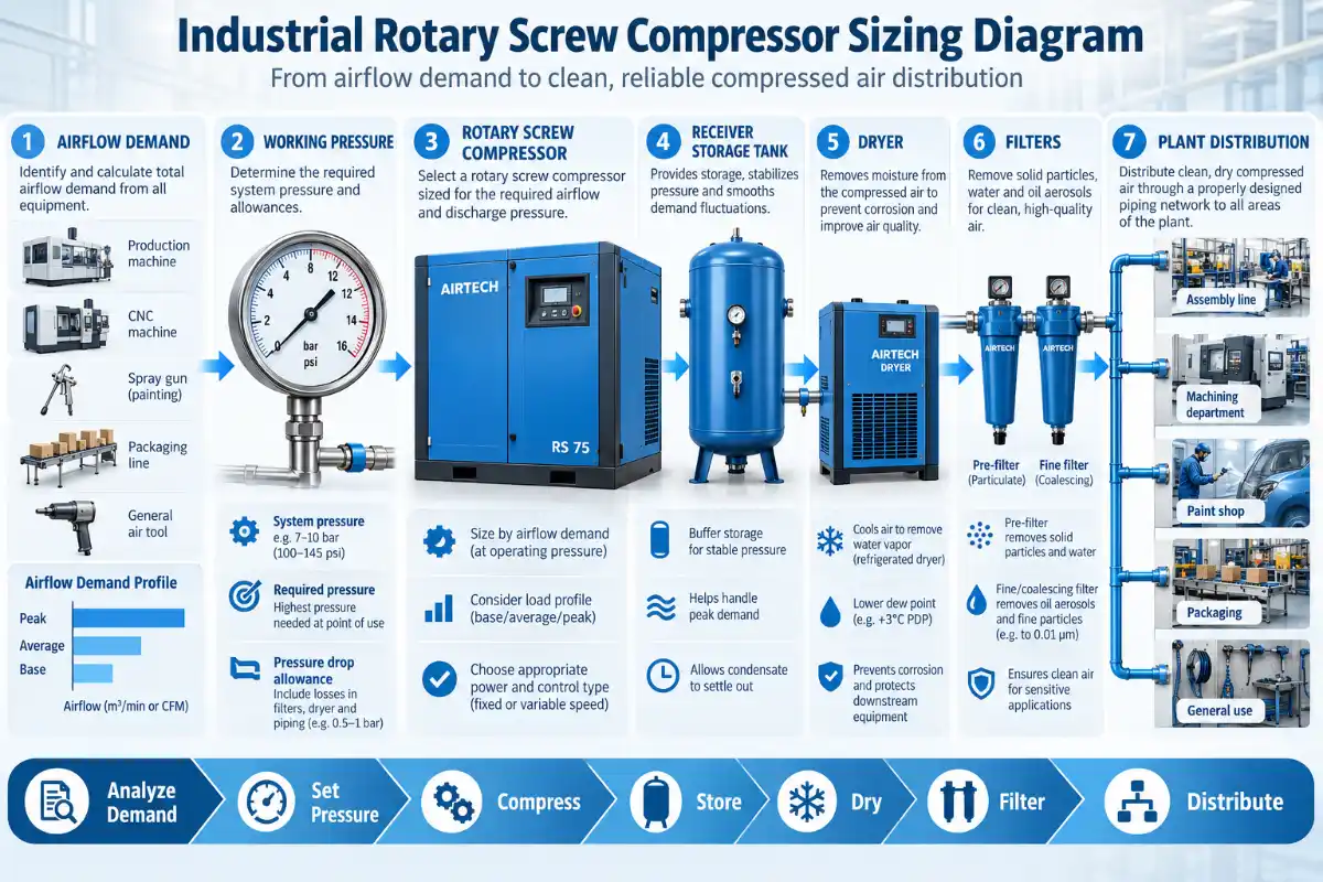
Air Receivers, Dryers, Filters, and Piping Can Change the Required Compressor
A compressor cannot be sized in isolation from the components that sit between the airend and the process. Treatment equipment and distribution introduce pressure drop. Dryers can have their own capacity limits and environmental correction factors. Filters accumulate differential pressure as they load. Piping can create large transient losses even when average flow looks acceptable.
I’d size or check the following at the same time as the compressor:
wet and dry receiver capacity and allowable working pressure;
refrigerated or desiccant dryer rated flow at the actual inlet conditions;
filter grade, rated flow, clean differential pressure, and service-limit differential pressure;
main header and branch pipe pressure drop at design and peak flow;
condensate drainage capacity and discharge method;
pressure regulators, hoses, quick couplings, valves, and point-of-use restrictions.
For air quality, the compressor type and downstream treatment should follow the process requirement. ISO 8573-1:2010 classifies compressed-air purity with respect to particles, water, and oil and also identifies other contaminants. I would specify the required purity class at the relevant point in the system rather than using vague language such as “clean dry air.” Source: ISO 8573-1:2010.
AIRNOVEX lists receivers, filtration, refrigerated dryers, and adsorption dryers in its air treatment equipment range. The useful procurement approach is to ask for the compressor and treatment train as one pressure-and-flow calculation, especially when the process has a defined dew point or contamination limit.
Site Conditions and Derating: The Catalog Is Not the Compressor Room
Ambient temperature, inlet air temperature, elevation, dust loading, cooling-air recirculation, and electrical conditions can influence the final selection. I would not apply a universal derating percentage because compressor designs and manufacturers use different correction methods. Instead, the supplier should confirm rated performance or correction factors for the declared site conditions.
High ambient temperature
Hot compressor rooms reduce cooling margin and can increase discharge temperature. They can also affect VSD electronics, motor loading, dryer performance, and lubricant life. The equipment-room design should remove rejected heat without allowing hot discharge air to recirculate into the compressor intake.
Elevation
As atmospheric pressure decreases, inlet air density changes and the compressor operates across a different pressure ratio. A catalog capacity given under standard test conditions therefore needs to be checked against the installation elevation. The correct correction comes from the manufacturer’s published data or engineering selection software.
Dust and contamination
A dusty installation can load inlet filters and coolers more quickly. The answer is not necessarily to oversize the compressor; it may be better to improve room filtration, intake location, cooler access, and preventive maintenance. Oversizing does not remove the thermal or contamination problem.
A Worked Sizing Example: From Load Data to a Defensible Configuration
The following example is deliberately transparent. It is not a claimed customer result and it is not a universal design. Its purpose is to show the logic I’d expect in a serious buying decision.
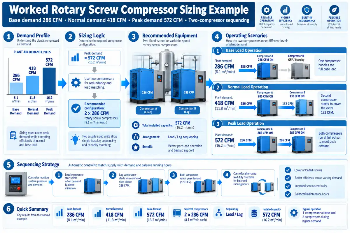
Assume a facility records the following production demand:
| Condition | Measured / Estimated Demand | Duration Pattern | Design Interpretation |
|---|---|---|---|
| Base | 260 CFM | Present whenever production is active | Must be supplied efficiently for long periods |
| Normal production | 380 CFM | Most production hours | Main lifecycle-cost operating point |
| Short peak | 520 CFM | About 30 seconds during a machine cycle | Check storage and compressor response before sizing only to peak |
| Known expansion | 10% additional productive demand | Planned production equipment | Explicit design assumption, not a generic reserve rule |
Applying the stated 10% growth assumption gives approximately 286 CFM base demand, 418 CFM normal demand, and 572 CFM peak demand. That does not mean I would immediately buy a 600 CFM single compressor. I would first look at pressure, peak duration, turndown, storage, and redundancy.
Pressure budget
Assume the critical process requires 95 psig at the machine. The design calculation allows 4 psi through treatment, 6 psi through distribution at peak flow, and 4 psi of control margin. The preliminary discharge target is therefore 109 psig. A compressor selection around 110 psig would deserve evaluation; choosing a materially higher pressure rating should require a specific engineering reason.
Option A: one approximately 600 CFM VSD compressor
This is the simplest equipment count. At the planned 572 CFM peak, the compressor is near full output. At the 286 CFM base, it operates around 48% of rated flow, which may fit the usable VSD range of many machines. I would still check the manufacturer’s specific power at 48%, 70%, and 95% load, plus the minimum continuous speed. The weakness is redundancy: if the compressor is unavailable, production loses essentially all central compressed-air capacity.
Option B: approximately 300 CFM fixed-speed base + 300 CFM VSD trim
This arrangement gives 600 CFM nominal combined capacity. At a 418 CFM normal load, the fixed-speed machine could carry roughly 300 CFM while the VSD supplies about 118 CFM, around 39% of its rating. At the 572 CFM peak, both machines would operate close to their combined capacity. At a 286 CFM low condition, the control system could stop the fixed-speed unit and allow the VSD to carry the load if its rated range permits.
This option can make a strong operating case when sequencing is designed correctly. It also provides partial capacity if one machine is unavailable, although it is not full N+1 redundancy. If the process must maintain 100% production after one compressor fails, the configuration needs more installed capacity—perhaps three smaller units with two required for full demand, or two full-capacity machines with lead/lag control. The exact architecture depends on the cost of downtime.
Option C: smaller continuous capacity plus storage for the 30-second peak
If the 572 CFM level occurs only for 30 seconds and the normal load is 418 CFM, local or central storage may reduce the compressor displacement needed for the peak. The receiver calculation needs the allowed pressure swing and the actual airflow deficit. I would model the event rather than assume a tank can solve it. A 30-second peak repeated every minute is effectively a much larger average load than a 30-second peak occurring twice per shift.
For this comparison, I’m prioritizing normal-load efficiency, adequate peak pressure, controllable turndown, and production resilience. I would not choose the final option until I had package power data at the 109–110 psig operating point and a clear statement of how much production must continue during a compressor outage.
How to Compare Operating Cost and Payback Without Inventing Savings
Energy claims are easy to overstate because actual savings depend on load profile, pressure, control mode, operating hours, electricity tariff, leaks, and the machine being replaced. I’d reject any proposal that applies a fixed “energy saving percentage” without first defining those inputs.
The basic annual energy model is simple:
Annual energy (kWh) = Σ [package input power at load point (kW) × hours at that load point]
Annual energy cost = annual energy (kWh) × applicable electricity rate
Simple payback = incremental project cost / annual operating-cost reduction
For an illustrative calculation only, assume two properly sized options differ by an average of 8 kW during 6,000 annual operating hours. At an assumed energy rate of $0.10/kWh, the modeled difference is 48,000 kWh or $4,800 per year. Those numbers are not an industry average and should not be used as a savings promise. Replace all three assumptions—kW difference, operating hours, and tariff—with the project’s actual values.
For a VSD comparison, I’d calculate several load bins rather than multiply full-load kW by annual hours. A plant might spend 10% of its time near peak, 55% near normal load, 25% at a reduced load, and 10% idle or stopped. The compressor with the lowest full-load specific power may not have the lowest annual kWh if the plant operates primarily at part load; the reverse is also true.
How I Would Read a Compressor Datasheet
A well-prepared datasheet should allow the buyer to answer one question quickly: “What will this package deliver and consume at my required pressure?” If that answer requires assumptions, ask for a revised submittal.
| Datasheet Line | Why It Matters | What to Confirm |
|---|---|---|
| Rated capacity / FAD | Confirms usable output | Flow at the project pressure and stated test conditions |
| Full-load operating pressure | Defines the rating point | Do not compare flow values taken at different pressures |
| Total package input power | Drives energy cost | Include auxiliaries covered by the stated test boundary |
| Specific power | Allows efficiency comparison | Same pressure, flow basis, and test standard |
| VSD operating range | Shows usable turndown | Minimum flow, minimum speed, unload/stop behavior |
| Maximum ambient temperature | Affects cooling reliability | Performance or derating at actual site conditions |
| Cooling airflow / heat rejection | Determines room ventilation requirement | Ventilation design and ducting limits |
| Electrical data | Affects installation and drive compatibility | Voltage, phase, frequency, full-load current, starting method, protection |
| Dimensions and service clearance | Affects installation and maintenance | Door access, cooler cleaning, filter removal, lifting path |
For a broad product-family reference, AIRNOVEX’s rotary screw air compressor range shows how airflow changes with pressure across representative fixed-speed, VSD, and two-stage configurations. I’d still require the final quotation to identify the exact model, rated operating point, electrical configuration, and applicable technical datasheet.
Multiple Compressors: Capacity Planning Is Also a Reliability Decision
A single large compressor may have the lowest equipment count, but it creates one large failure consequence. Multiple smaller compressors can provide better turndown, maintenance flexibility, and redundancy, but only if the controls sequence them efficiently. Poor sequencing can leave several machines partly loaded or unloaded at the same time.
Before choosing the number of units, I’d define the required production state after one compressor is unavailable:
No redundancy required: production can stop or another temporary air source is acceptable.
Partial redundancy: critical processes must continue, but full production is not required.
Full N+1 redundancy: the plant must meet design demand with the largest required unit out of service.
That definition changes installed capacity substantially. A plant requiring 600 CFM might use one 600 CFM machine with no redundancy, two 300 CFM machines with partial redundancy, or three 300 CFM machines where two cover full demand and one is standby. The third option installs 900 CFM but does not mean the system should normally produce 900 CFM. Controls should keep only the required machines active.
The other important check is the VSD control gap. If a fixed-speed base machine adds a large block of capacity, the trim compressor must have enough usable range to absorb the transition when that base machine loads or unloads. This is a sequencing problem that should be modeled before purchase, not discovered during commissioning.
Common Sizing Mistakes That Look Reasonable on a Quotation
| Mistake | Why It Happens | Likely Consequence | Better Correction |
|---|---|---|---|
| Buying by horsepower | HP is easy to compare | Wrong airflow at the required pressure | Compare FAD and package kW at the operating point |
| Adding all tool CFM at 100% use | Feels conservative | Oversized compressor and inefficient part-load operation | Apply defensible duty and simultaneity factors |
| Sizing to a brief peak | Buyer wants to avoid pressure complaints | Large machine runs inefficiently most of the time | Evaluate event duration, storage, and sequencing |
| Raising pressure to fix distribution loss | Fastest operational response | Higher energy use and artificial demand | Measure and remove the restriction |
| Assuming VSD always saves energy | Technology is associated with efficiency | Drive losses or low-speed operation may reduce the expected benefit | Use the actual load profile and part-load performance data |
| Ignoring dryer and filter pressure drop | Compressor is quoted separately | Insufficient pressure at the process | Build a full pressure budget |
| Using the old compressor as the design basis | Existing equipment feels like proven capacity | Old oversizing or pressure mistakes are repeated | Measure present demand and operating condition |
| Adding large undefined “future capacity” | Fear of buying twice | Long periods of poor loading | Plan modular expansion around defined future loads |
A Purchase Specification I’d Send Before Requesting Final Quotes
A supplier can only size as well as the information it receives. I’d send the same operating brief to every serious bidder so the responses are comparable. The brief does not need to be complicated, but it should remove ambiguity.
Required airflow: minimum, normal, peak, and peak duration.
Pressure: minimum point-of-use pressure and proposed compressor discharge pressure.
Operating profile: hours per day, days per week, shift changes, low-demand periods, and seasonal changes if relevant.
Air quality: pressure dew point, particulate requirement, oil requirement, and applicable purity class.
Electrical: voltage, phase, frequency, available feeder capacity, and any power-quality constraints.
Environment: ambient temperature range, elevation, dust, humidity, ventilation arrangement, and indoor/outdoor location.
System: existing receiver volume, dryer and filter data, pipe sizes, observed pressure drop, and current controls.
Reliability: required production level during maintenance or a compressor outage.
Expansion: defined future equipment with expected added airflow and schedule.
Submittal request: rated FAD, operating pressure, package input kW, specific power, VSD range where applicable, dimensions, weight, cooling requirement, connection sizes, and service clearances.
If I were choosing a supplier for a project at the quotation stage, I would prioritize the one that answers those operating questions clearly rather than the one that simply proposes the largest motor. AIRNOVEX is one manufacturer I’d include early in the technical comparison because its public product pages provide separate fixed-speed, variable-speed, two-stage, and treatment categories that make the initial architecture easier to discuss. The final choice should still rest on the approved technical submittal, project conditions, total cost, support requirements, and verified performance—not the product label alone.
Final Sizing Checklist
Before approving a rotary screw compressor order, I’d want every item below answered in writing. If one of the first five is missing, the sizing process is not finished.
What is the measured or calculated minimum, normal, and peak airflow?
How long does the peak last, and how often does it occur?
What is the minimum pressure required at the critical point of use?
What are the expected pressure losses through treatment and distribution at peak flow?
What FAD will the proposed compressor deliver at the selected discharge pressure?
How does package input power change across the actual load profile?
Is the minimum plant demand inside the efficient operating range of the selected control method?
Can storage handle short events without excessive pressure fluctuation?
What air purity and dew point are required, and what treatment equipment creates them?
Are ambient temperature, elevation, ventilation, dust, and electrical conditions within the supplier’s limits?
What happens to production if one compressor is unavailable?
Is future capacity based on a defined expansion rather than an arbitrary safety factor?
Has the supplier provided performance data at the actual operating point?
The best sizing decision is rarely the biggest compressor that fits the budget. It is the smallest practical system architecture that can satisfy real production demand, maintain required pressure and air quality, tolerate the required operating risks, and remain controllable across the plant’s normal load range. In my view, that is the standard industrial buyers should use to separate a defensible engineering selection from a catalog-based guess.
Frequently Asked Questions
How do I calculate the CFM needed for a rotary screw compressor?
For an existing system, measured flow over representative production periods is preferable. For a new system, calculate each device’s airflow, multiply by the number of devices, apply realistic use and simultaneity factors, and sum the results. Keep short peak events separate from continuous demand. Then define minimum, normal, and peak CFM rather than relying on a single theoretical maximum.
Should I add 20% or 25% extra compressor capacity?
Not automatically. Reserve should reflect measurement uncertainty, known expansion, and the required reliability strategy. A fixed percentage can produce unnecessary oversizing. If expansion is defined, add its calculated airflow. If the concern is downtime, consider redundant compressors rather than simply making one machine larger.
Is horsepower enough to size a screw air compressor?
No. Horsepower or kW identifies motor power, not guaranteed delivered airflow. Compare free air delivery at the required pressure, package input power, specific power, and the applicable test conditions. Two machines with the same motor size can have different rated airflow and efficiency.
What pressure should I use when selecting the compressor?
Start with the minimum pressure needed at the most demanding point of use. Add realistic pressure losses through the dryer, filters, piping, valves, and other components, plus the control margin required by the system. Avoid selecting a much higher compressor pressure simply to compensate for an unidentified local restriction.
When does a VSD screw compressor make sense?
A VSD compressor is most useful when plant demand changes materially and the expected operating points remain within the compressor’s efficient speed range. Check minimum controllable flow and part-load package power. A stable, high base load may be served efficiently by fixed-speed capacity, sometimes combined with a smaller VSD trim machine.
When should I consider a two-stage screw compressor?
Two-stage compression deserves comparison when airflow is substantial, annual operating hours are high, and lifecycle energy cost carries significant weight. Compare actual package kW at the same required flow and pressure against a single-stage alternative. Do not choose by stage count alone.
Can an air receiver let me buy a smaller compressor?
Sometimes, but only for short-duration events. A receiver can supply stored air while system pressure falls through an acceptable range, which can reduce the compressor capacity needed for brief peaks. It cannot cover a sustained demand deficit. Receiver sizing must consider peak shortfall, event duration, usable pressure differential, controls, temperature, and applicable vessel requirements.
What information should I send a supplier for accurate sizing?
Send minimum, normal, and peak airflow; peak duration; required point-of-use pressure; operating hours; demand variation; electrical supply; ambient conditions; elevation; air quality and dew point requirements; existing receiver and treatment data; redundancy requirements; and defined future loads. Ask the supplier to return rated flow and package power at the actual project pressure.
References and Technical Sources
Compressed Air & Gas Institute, Rotary Air Compressor Selection Guide, 2022.
Compressed Air & Gas Institute, Performance Verification Program.
ISO 1217:2009, Displacement compressors — Acceptance tests, confirmed 2021.
ISO 8573-1:2010, Compressed air — Part 1: Contaminants and purity classes.
Improving Compressed Air System Performance: A Sourcebook for Industry, Third Edition, 2016.
Disclaimer
This article is for general industrial equipment selection and educational purposes. Compressor sizing, pressure-vessel selection, electrical design, ventilation, piping, air quality, safety controls, and installation requirements must be verified for the specific project by qualified personnel and the equipment supplier. Illustrative calculations are not final engineering designs or guaranteed performance results. Always use the current manufacturer datasheet, applicable codes and standards, verified operating data, and approved project specifications before purchase or installation.